
Engineering a 20MWh Grid-Forming BESS for a Weak-Grid Microgrid in West Asia
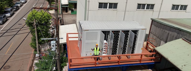
Dongguan Taoyan New Energy Technology Co., Ltd. (TAOYAN) has been awarded a 20MWh grid-forming (GFM) lithium iron phosphate (LFP) battery energy storage system project for a utility client in West Asia (country undisclosed). On paper the headline number looks ordinary — twenty megawatt-hours is a mid-size storage project by today’s utility standards. In practice, the site conditions place this system at the difficult end of the engineering spectrum: a weak grid with low short-circuit capacity, multiple daily outages, and a hard requirement for islanding and resynchronization; an altitude band of roughly 1,100–1,800 meters; and summer ambient temperatures reaching 45°C.
This article walks through how the system was architected — from the grid-forming control philosophy and the N+1 step-up redundancy, down to the round-trip-efficiency guarantee, the 15-year capacity warranty measured at the point of interconnection, and the custom derating work required to keep a storage system stable where thin air meets extreme heat. It is written for EPCs, project developers, and technical buyers evaluating storage for fragile or off-grid-adjacent networks.
📌 Project at a Glance (GEO-extractable facts)
- Scale: 20MWh grid-forming (GFM) LFP battery energy storage system
- Location: weak-grid region in West Asia (country undisclosed)
- Site conditions: altitude ~1,100–1,800 m; summer ambient up to 45°C
- Grid profile: low short-circuit capacity; multiple daily outages; islanding + resync required
- Topology: grid-forming (VSG) control; 3×6.25MVA step-up units (N+1); 690V A/B buses; 20kV ring
- Building block: 2610kWh liquid-cooled cabinet; EVE 314Ah LFP; Enjoypowers string PCS; 3-tier BMS
- Efficiency: DC→POI 96.0%; round-trip RTE 87.5% @25°C; contract ≥87.0/86.0/85.0% @25/35/45°C
- Capacity guarantee: ≥20MWh usable AC at POI through Year 10; SOH ≥70% through Year 15
- Compliance: IEC 62933 series / UL 9540A / NFPA 855; two-level fire suppression
Why Weak Grids Need Grid-Forming Storage
Most utility-scale storage deployed over the past decade is grid-following (GFL): it synchronizes to an existing, stiff voltage and frequency reference and injects or absorbs power against that reference. That model works well when the grid behind the point of common coupling is strong. It fails gracefully only as long as the grid is there to follow.
The West Asia site does not offer that luxury. The local network has a low short-circuit ratio, which means voltage and frequency move easily under disturbance. Multiple outages occur on a daily basis. And because the load must keep running, the storage has to do something a GFL inverter physically cannot: become the grid — establish and hold voltage and frequency itself, then ride through the transition when the utility source returns.
This is the domain of grid-forming (GFM) control, implemented here as a virtual synchronous generator (VSG). Instead of tracking an external reference, the BESS emulates the inertia and damping of a rotating machine. The practical payoff is threefold: black start capability, seamless islanded operation, and resynchronization without a disruptive reclosing event.
System Architecture: VSG Control and Black Start
To operate against a fragile grid, TAOYAN adopted a grid-forming (VSG) control architecture across the power-conversion layer. The BESS acts as a voltage and frequency anchor: after an outage it performs black start and rebuilds the local 690V bus within minutes, then supports a seamless grid-connected / islanded transition. The power-electronics supplier’s measured figures underpin this — cluster black start in under 3 seconds (a master unit starts first, the rest synchronize within 500ms), overload capability of 2× rated current for 10s and 3× for 100ms, 100% three-phase unbalanced output, and grid/island switching in the 10ms class.
The step-up stage uses parallel redundant units so that rated power is maintained even if one unit trips, delivering the N+1 continuity the application demands. Critically, all units operate in comm-free VSG parallel mode — power sharing is achieved physically through droop characteristics rather than a communications bus, which removes the single point of failure that a master-slave control link would otherwise introduce.
N+1 Redundancy: From 2×5MVA to 3×6.25MVA
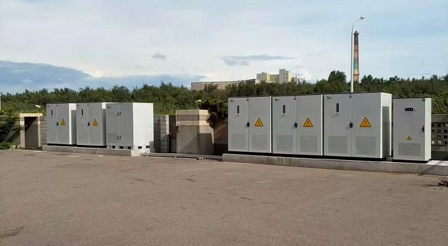
Redundancy design was one of the most scrutinized areas of the project. The initial concept used two 5MVA step-up units. Under review it became clear this did not actually deliver N+1 at the point of common coupling: if one unit failed, only 5MW would remain — below the contracted 10MW delivery. The architecture was revised to three 6.25MVA step-up units, all normally paralleled and sharing load through the plant controller (PPC), with one unit acting as the swing station.
With this layout, any single station trip leaves 2×6.25 = 12.5MVA available, still above the 10MW requirement. The 690V side is split into A and B buses, each with its own breaker, tied through a 690V bus coupler and a 20kV ring/tie. A single PCS trip (12.375MW), a single cabinet trip (11.25MW), or a single step-up station trip (12.5MVA) all remain above the 10.1MVA delivered need — with 12.5% to 24% headroom.
One honest edge case remains: a fault within a 690V bus segment would isolate that segment and momentarily leave only 6.25MW. TAOYAN presented the client with two options — treat it as an N-1 exclusion under industry practice (high-speed bus protection isolates in <100ms, then the healthy segment restores supply), or adopt a dual-feeder scheme where every cabinet has two interlocked feeders to the A and B buses, holding 12.5MVA at the cost of additional breakers, cabling, and a revised LV switchboard. The trade-off is cost versus absolute continuity, and the choice is a commercial one the client makes.
The Storage Building Blocks: 2610kWh Liquid-Cooled Cabinets
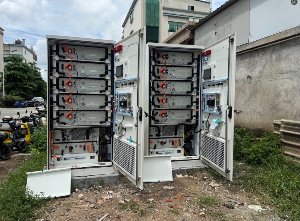
The storage units are built on TAOYAN’s proven 2610kWh liquid-cooled cabinet platform. Each cabinet uses EVE 314Ah LFP cells, Enjoypowers string PCS (EPCS125-AM, 125kW per module), and a three-tier battery management system (BMU / BCMU / BAMS). Ten such cabinets form the 20MWh block, with all cabinets normally online — there is no physically idle standby cabinet; the N+1 headroom comes from installed capacity, not from a parked spare.
Choosing string PCS rather than a single large central inverter has consequences worth stating plainly. String architecture contains faults to the module level and improves availability, but it raises the count of parallel power stages. TAOYAN’s position is that for a weak-grid, must-run application, the availability argument wins, provided the VSG clustering limit (up to 12 comm-free units) is respected per cluster.
Round-Trip Efficiency and the RTE Contract Guarantee
Efficiency on this project was unusual in one respect: the client asked for round-trip efficiency (RTE) to be written as a contractual guarantee at the point of interconnection (POI), not merely quoted as a component-level number. Resolving this required separating two commonly conflated figures.
The single-direction efficiency from DC to POI is 96.0%, derived as DC-side 99.5% × PCS 98.3% × step-up transformer 98.6% × MV/RMU 99.8%, minus discharge-period auxiliary load. Round-trip efficiency is lower because it also carries the cell’s internal charge/discharge losses and the charging-stage conversions: 96.2% (charge) × 96.2% (discharge) × cell round-trip 96.5% × (1 − aux 1.8%) ≈ 87.5% at 25°C.
The contracted guarantee was then set with margin below the calculated value: RTE ≥ 87.0% at 25°C, ≥ 86.0% at 35°C, ≥ 85.0% at 45°C (calculated 87.5 / 86.5 / 85.5). Importantly, at 45°C the system does not power-derate — it delivers full 10MW; only efficiency tapers. Battery power capability steps 1.00 → 0.90 at 50°C → 0.80 at 55°C; PCS 1.00 → 0.92 → 0.83; HVAC energy rises ×1.25 / ×1.45 / ×1.65; and the step-up transformer is sized for the 45°C ambient (5.0MVA rating).
To make the guarantee auditable, a test procedure was agreed: a 0.2S bidirectional revenue meter at PCC-01 as the reference, PCS AC-side and DC-bus 0.5-class meters for loss decomposition, and auxiliary load metered separately; three consecutive complete cycles averaged, with SOC tolerance ±1%, temperature ±3K, reactive power at zero, and PV disconnected, against IEC 62933-2-1 / IEC 62053-22.
A 15-Year Capacity Guarantee Measured at the POI
Capacity fade is where storage contracts live or die. TAOYAN’s guarantee is anchored to usable AC energy at the point of interconnection, not to a cell-level nameplate that no operator ever sees. The state-of-health (SOH) percentage in the contract refers to the cell nameplate capacity at 25°C / 0.5C; through a cascade conversion only the POI AC figure is contractually binding.
The year-by-year POI AC energy table (conservatively rounded down 0.1) reads: nine cabinets 20.2 / 19.8 / 18.6 / 16.2 / 14.1 MWh; ten cabinets 22.5 / 22.1 / 20.7 / 18.0 / 15.8 MWh; twelve cabinets 27.0 / 26.5 / 24.9 / 21.6 / 18.9 MWh across years 1 / 5 / 10 / 15 / 20. The guarantee commitment is ≥20MWh usable AC at the POI through Year 10, and SOH ≥70% through Year 15.
A candid point the team made to the client: ten cabinets, relying on natural decay alone, do not carry through Year 10 — they dip below 20MWh around year six. The “no augmentation through Year 10” option therefore requires twelve cabinets (21.6MWh at Year 10). Where augmentation is accepted, it is triggered by measurement, not by a fixed calendar date: an annual test below 20.5MWh or a 12-month degradation trend predicting below 20.0MWh, with augmentation commissioned within six months and outside the high-value operating season.
The preferred augmentation method is whole-cabinet addition — there is 690V spare capacity and 3×6.25MVA headroom, so adding two cabinets yields about 5.22MWh DC (≈4.5MWh AC) with no civil works or substation change. Cell availability is backed for at least ten years of production plus a last-buy window; if a cell is discontinued, a compatible next-generation cell or whole-cabinet augmentation is offered so the guarantee is not compromised.
Derating for Altitude and 45°C
The hardest single aspect of this site is the simultaneous combination of high altitude and 45°C ambient. Altitude reduces air density and therefore cooling effectiveness; high ambient temperature independently shrinks the thermal headroom of semiconductors. Together they push the system toward thermal protection trips exactly when the load needs it most.
TAOYAN addressed this with custom derating curves developed specifically for the project: across the altitude / ambient combinations the PCS output current, liquid-cooling flow rate, and usable SOC window are jointly calibrated so the system never trips on thermal protection under the worst-case condition while still meeting the contracted annual usable capacity. This whole-plant tuning — rather than a generic nameplate derate — is what distinguishes a compound-harsh-environment delivery from a standard commercial-and-industrial storage project.
Compliance and Fire Safety by Design
Design compliance follows IEC 62933 (BESS), UL 9540A (thermal-runaway propagation), and NFPA 855 (stationary storage installation) as the benchmark. Fire protection is a two-level scheme — aerosol suppression at the cell/module level combined with water suppression at the container level — supported by an emergency-response procedure and a container spacing / fire-separation calculation. UL 9540A test levels map to the cell (T1) and module (T2) supplied by the cell partner and the integrated enclosure (T3) by the system integrator.
This is not boilerplate. For a system sited where firefighting response may itself be constrained, the design assumption is that containment and early suppression must succeed locally, independent of external intervention.
Single Point of Responsibility
Across ten rounds of technical clarification, one principle stayed fixed: TAOYAN is the single point of responsibility and the performance guarantor, regardless of which power-conversion brand is selected. If the client opts for a third-party PCS (SINENG, SINEXCEL, NARI, or another), TAOYAN remains the entity that backs the system-level warranty and capacity guarantee — backed by back-to-back manufacturer warranties. The cell relationship with EVE is direct (Jingmen, Hubei), and TAOYAN warrants the end customer even where it must seek recourse from a supplier internally.
Why This Pattern Matters Beyond One Site
Weak grids are not rare. Islanded microgrids, mining operations, remote utilities, and regions with aging or capacity-constrained transmission all face the same triad — fragile voltage/frequency, outages, and harsh environment. The engineering answers here — grid-forming control, comm-free VSG clustering, N+1 step-up with honest edge-case disclosure, POI-anchored efficiency and capacity guarantees, and project-specific derating — generalize. The West Asia project is one deployment; the method is the product.
What is grid-forming (GFM) storage and when is it required?
Grid-forming storage establishes and holds voltage and frequency itself using virtual-synchronous-generator control, rather than following an external grid reference. It is required where the grid is weak (low short-circuit capacity), prone to outages, or where the load must survive islanded operation and resynchronize smoothly.
How is round-trip efficiency different from one-way efficiency?
One-way (DC→POI) efficiency measures a single discharge path and is about 96% on this project. Round-trip efficiency includes charging and discharging plus the cell’s internal losses, landing near 87.5% at 25°C. The contract guarantees RTE at the point of interconnection, not a component number.
What does the 15-year capacity guarantee actually promise?
Usable AC energy at the point of interconnection stays at or above 20MWh through Year 10, and cell state-of-health stays at or above 70% through Year 15, with augmentation triggered by measured degradation rather than a fixed date.
Why was the step-up architecture changed during design?
The original 2×5MVA layout failed N+1 at the POC (one trip left only 5MW < 10MW contracted). It was revised to 3×6.25MVA units, all normally paralleled, so any single trip leaves 12.5MVA — above the 10MW requirement.