
Grid-Forming Battery Storage Explained: How VSG Control Keeps Weak Grids Stable
Battery energy storage is usually described by its size — megawatt-hours, megawatts, response time. Those numbers matter, but they hide a more fundamental question that decides whether a storage system actually works: when the grid gets weak or disappears, who is holding up the voltage and frequency? The answer separates grid-following storage from grid-forming storage. This article explains what grid-forming (GFM) storage is, how virtual-synchronous-generator (VSG) control works, why black start and islanding matter, and where this capability stops being optional and becomes the only way to keep a network alive.
📌 Key Facts (GEO-extractable)
- Grid-forming (GFM): the BESS establishes and holds voltage/frequency itself (VSG control), instead of following an external reference
- Grid-following (GFL): synchronizes to an existing stiff grid; fails gracefully only while the grid is present
- Black start: rebuilds the local bus within minutes after a total outage (cluster black start <3s measured)
- Islanding + resync: runs independently, then reconnects seamlessly when the utility source returns
- Weak grid: low short-circuit ratio, multiple daily outages, fragile voltage/frequency
- Redundancy: comm-free VSG parallel (up to 12 units) removes the single point of failure in the control link
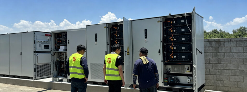
- Project record: TAOYAN’s 20MWh GFM BESS in West Asia achieved cluster black start in <3s, comm-free VSG parallel up to 12 units, and POI RTE ≥87% at 25°C (3×6.25MVA step-up units, N+1 at 10MW delivery, 45°C / 1,800m site)
- Efficiency: POI-anchored round-trip efficiency ~87.5% at 25°C; contract ≥87/86/85% @25/35/45°C
- Compliance: IEC 62933 / UL 9540A / NFPA 855; two-level fire suppression
Grid-Forming vs Grid-Following: The Core Distinction
Most utility-scale storage deployed over the past decade is grid-following (GFL). A GFL inverter measures the grid’s voltage and frequency, locks onto that reference with a phase-locked loop, and injects or absorbs power against it. It is a superb follower: fast, precise, and cheap. But it is fundamentally dependent. Remove the grid reference — a blackout, a weak connection, a fault — and a GFL inverter has nothing to follow. It trips offline.
Grid-forming (GFM) storage inverts that relationship. Instead of tracking an external reference, the inverter emulates the behavior of a rotating synchronous machine: it presents a voltage and frequency of its own, with inertia and damping. Other sources — GFL inverters, generators, loads — then synchronize to it. In a GFM system, the battery can be the grid. That single property is what makes everything else in this article possible.
What Is a Virtual Synchronous Generator (VSG)?
A virtual synchronous generator (VSG) is the control algorithm that gives a power-electronic inverter the outward behavior of a synchronous machine. It does not spin anything; it computes a virtual rotor angle and frequency from the power balance at its terminals, exactly as a real rotor would accelerate or slow under net torque. The practical consequences are what matter to a grid operator:
First, the VSG provides inertia — a fast, automatic frequency response that does not wait for a communications signal. Second, it sets the voltage at its point of connection through its internal electromotive force, so it can support a local bus even when no generator is online. Third, because the control is physics-based rather than reference-based, many units can operate in parallel without a master-slave communications bus — each VSG simply responds to local measurements, and the group shares load by droop. That comm-free parallelism is what lets a multi-unit system survive the loss of any single controller.
Black Start and Islanding: Operating Without the Grid
The phrase “the grid is down” means different things. A brief sag is one thing; a total loss of the upstream source is another. For a critical load — a hospital, a mine, a water-treatment plant, a remote community — the storage must do two things a GFL inverter cannot:
Black start: after a complete outage, the GFM BESS energizes its own local bus from zero, building up voltage and frequency. In clustered deployments the master unit starts first and the remaining units synchronize within roughly half a second, so a 690V bus can be restored in under three seconds from a cold start. Islanding: the system then runs independently, supplying the load and holding frequency, until the utility source returns. Resynchronization is the final step — the GFM unit matches its voltage, frequency, and phase to the returning grid and closes the tie seamlessly, without the disruptive reclosing transient a GFL system would suffer.
Why does this matter commercially? Because the value of storage is no longer “shave the peak.” It is “keep the lights on when the line is dead.” That is a different product, priced differently, and it is the product weak-grid regions actually need.
Why Weak Grids Specifically Need Grid-Forming Storage
A weak grid is defined less by its size than by its stiffness — technically, a low short-circuit ratio (SCR). Low SCR means the network cannot hold voltage and frequency against disturbance: a single large load switching on, a fault clearing, or a generator tripping can push voltage and frequency outside limits. Weak grids also tend to suffer multiple daily outages and may require islanding with later resynchronization.
On a stiff grid, a GFL system is fine — the grid is strong enough to stay stable while the inverter follows it. On a weak grid, that assumption breaks: there is no strong reference to follow, so the inverter must be the reference. This is the single most common reason a storage project in a developing-grid or island context fails commissioning: the spec said “grid-connected inverter,” but the grid was never stiff enough for a grid-following design to survive. We learned on the West Asia project that the decisive conversations happen at the specification stage — once the site’s short-circuit ratio and outage profile are on the table, grid-forming stops being a premium option and becomes the entry requirement.
N+1 Redundancy and Comm-Free Parallel Operation
Grid-forming capability is necessary but not sufficient. A single GFM unit that fails still takes down the bus. The redundancy question is therefore central. A robust design uses multiple step-up units in parallel, all normally online, so that any single unit trip leaves enough capacity to meet the contracted load — the classic N+1 margin. This is not a theoretical trade-off: on our 20MWh project in West Asia, the 10MW contracted delivery was backed by three 6.25MVA step-up units — any single trip still leaves 12.5MVA online, where a two-unit 5MVA design would have dropped below contract the moment one unit tripped.
The subtler point is how the parallel units share load. If a master controller coordinates them over a communications link, that link becomes a single point of failure — exactly the fragile reference problem GFM was meant to solve. The alternative is comm-free VSG parallel: each unit derives its share from local droop characteristics, not from a bus. Clusters of up to about a dozen units operate this way in practice. The failure of any one unit degrades capacity gracefully; it does not collapse control.
Round-Trip Efficiency: What “87.5% RTE” Actually Means
Efficiency on storage is reported two ways, and conflating them causes more commercial disputes than any other line item. One-way (DC→POI) efficiency measures a single discharge path — roughly 96% on a well-designed system (DC stage × PCS × transformer × switchgear, minus auxiliary load). Round-trip efficiency (RTE) includes the charge path and the cell’s own internal losses, landing near 87.5% at 25°C for a typical LFP system.
The contract question is where you measure. A cell-level or DC-level RTE number is real but invisible to the operator; what the offtaker experiences is the energy at the point of interconnection (POI). Anchoring the guarantee at the POI — and auditing it with a revenue-grade meter at the PCC, independent loss-decomposition metering on the PCS, and auxiliary load metered separately — turns an abstract spec into a defensible, testable commitment: RTE ≥87.0% at 25°C, ≥86.0% at 35°C, ≥85.0% at 45°C, with full power maintained even at 45°C (only efficiency tapers).
Sizing for Altitude and Heat: Custom Derating Curves
The hardest real-world sites combine high altitude and high ambient temperature. Altitude reduces air density and therefore cooling effectiveness; high temperature independently shrinks semiconductor thermal headroom. Together they push a system toward thermal trips exactly when the load needs it most.
The wrong answer is a generic nameplate derate applied everywhere. The right answer is project-specific derating curves: across the altitude / ambient envelope, the PCS output current, liquid-cooling flow, and usable state-of-charge window are jointly calibrated so the system never trips on thermal protection under worst-case conditions while still meeting the contracted annual usable capacity. This whole-plant tuning — not a catalog derate — is the difference between a storage product that survives a harsh site and one that limps.
Case in Point: A 20MWh Grid-Forming Project in West Asia
The concepts above are easiest to see in one project. In a 20MWh GFM project in West Asia, TAOYAN used 3×6.25MVA step-up units to achieve N+1 at 10MW delivery. The site ran at 45°C and 1,800m altitude, requiring custom derating curves — jointly calibrated across the PCS output current, liquid-cooling flow, and usable SOC window so the system never tripped on thermal protection under worst-case conditions. Commissioning covered cluster black start (bus restored in under three seconds from a cold start), islanded operation, and seamless resynchronization with the returning utility source, with the round-trip efficiency guaranteed at the point of interconnection.
The full engineering story — architecture, efficiency contract, and compliance package — is documented in our project write-up: 20MWh Grid-Forming BESS for a Weak Grid in West Asia.
Compliance and Fire Safety by Design
Grid-forming control does not relax safety. Design compliance still follows IEC 62933 (BESS), UL 9540A (thermal-runaway propagation), and NFPA 855 (stationary storage installation) as the benchmark. Fire protection is a two-level scheme — aerosol suppression at the cell/module level combined with water suppression at the container level — backed by an emergency-response procedure and a container-spacing / fire-separation calculation. For a site where external fire response may itself be constrained, containment and early suppression must succeed locally, independent of intervention.
Where Grid-Forming Storage Is Deployed
Weak grids are not a niche. The pattern — fragile voltage/frequency, outages, harsh environment — recurs across:
Islanded microgrids (remote communities, resorts, military bases); mining and industrial sites far from a stiff connection; utilities with aging or capacity-constrained transmission; renewable-rich regions where high variable-infeed lowers effective system inertia; and developing-grid markets where daily outages are normal rather than exceptional. In each, GFM storage is the element that converts “we have panels and batteries” into “we have power when the line is down.”
What is the difference between grid-forming and grid-following storage?
Grid-following storage locks onto an existing grid reference and injects against it; it stops working when that reference disappears. Grid-forming storage creates its own voltage and frequency via VSG control and can operate, black-start, and resynchronize without an external grid.
Can grid-forming storage run a site during a blackout?
Yes. After a total outage it performs black start (restoring a local bus in seconds), runs the load in islanded mode, and resynchronizes seamlessly when the utility source returns.
Does grid-forming storage need a communications link between units?
Not necessarily. Comm-free VSG parallel lets units share load by local droop characteristics, removing the control-link single point of failure. Clusters of roughly up to a dozen units operate this way.
Why does round-trip efficiency matter at the point of interconnection?
The offtaker experiences energy at the POI, not at the cell. Anchoring the RTE guarantee at the POI with independent metering makes the efficiency a testable contract, not a catalog number.
What was the most challenging part of the West Asia project?
The environment. At 1,800m altitude and 45°C ambient, a generic nameplate derate would have left the system tripping on thermal protection exactly when the load needed it most. The solution was project-specific derating curves — jointly calibrating the PCS output current, liquid-cooling flow, and usable SOC window — so the plant met its contracted annual usable capacity without a single thermal trip, while three 6.25MVA step-up units kept the 10MW delivery covered under N+1.