
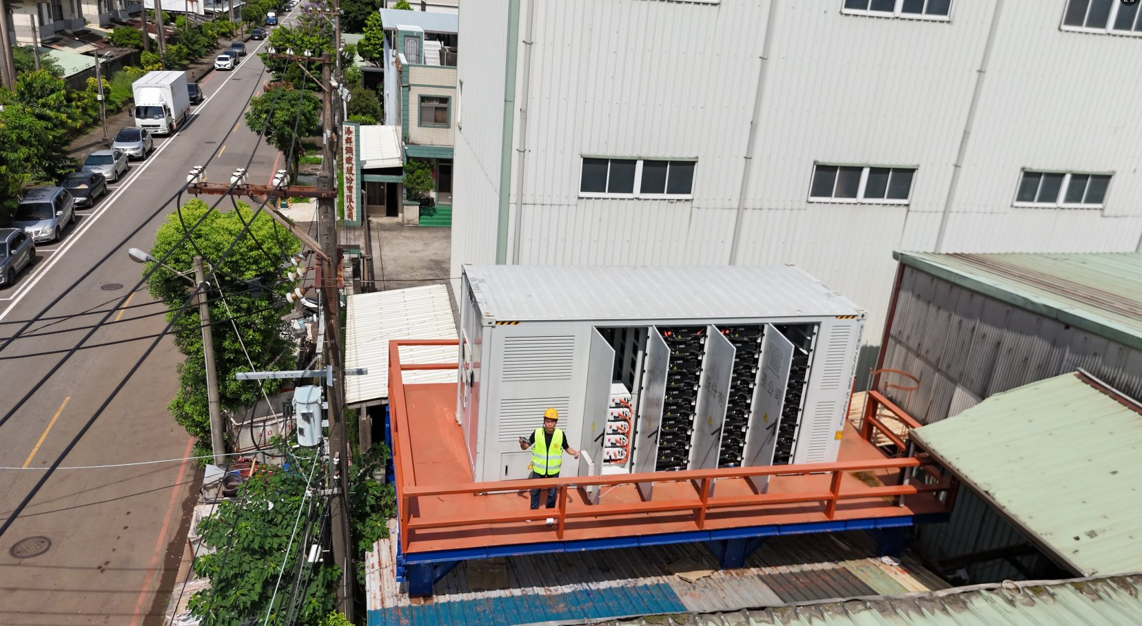
2610KWH-1250KW Solution
Project Description
This project delivers a 2.61MWh / 1.25MW grid-connected battery energy storage system (BESS) built around an advanced liquid-cooled lithium iron phosphate (LFP) architecture. The system is engineered for industrial-scale peak shaving, load shifting, and frequency regulation, enabling facilities to dramatically reduce electricity costs through intelligent energy time-of-use arbitrage.
The solution is housed in a single 20-foot ISO containerized unit featuring a dual-chamber design: a battery chamber with ten (10) strings of liquid-cooled LFP battery clusters (832V / 314Ah each), and a power conversion chamber housing a modular 1250kW PCS composed of ten parallel 125kW inverter modules. The integrated liquid thermal management system maintains optimal cell temperatures across a wide -25°C to 55°C operating range, delivering superior cycle life and round-trip efficiency compared to air-cooled alternatives.
Total Energy Capacity
Rated Output Power
20ft Container
PCS Efficiency
Cell Chemistry
Protection Rating
🔌 Key Innovation: Liquid-Cooled All-in-One Containerized BESS
This solution packs 2.61MWh of liquid-cooled LFP storage plus a 1250kW PCS into a single 20ft container. The liquid cooling system uses an integrated die-cast cold plate design that merges the cooling plate with the battery module enclosure, eliminating coolant leakage risk while achieving IP67 protection at the module level. Ten battery clusters (each 832V / 261.248kWh) connect via a centralized DC bus to ten 125kW PCS modules operating in parallel, delivering up to 1300kW peak output to the 400V AC grid with four-quadrant control and power factor >0.99. The result: industry-leading energy density, extended cycle life (≥8000 cycles), and rapid deployment with minimal site preparation.
- Liquid-Cooled LFP Battery System: Ten clusters of 832V / 314Ah LFP cells (2610 kWh total) using 3.2V prismatic cells with integrated die-cast liquid cooling plates. Each module (52S1P, 166.4V / 52.25kWh) achieves IP67 protection. Cycle life ≥8000 cycles at 80% DOD.
- Modular PCS Architecture: Ten × 125kW PCS modules (EPCS1250-AS) operate in parallel via centralized DC bus, delivering 1250kW rated / 1300kW maximum output. Four-quadrant active/reactive control, power factor >0.99, THD <3%.
- Advanced Thermal Management: Dual-circuit liquid cooling (refrigeration + heating) maintains battery temperature within optimal range. PTC heater ensures reliable charging in cold environments down to -25°C. Compressor-based refrigeration handles high-rate discharge heat rejection.
- Integrated Safety Systems: Multi-layer protection including three-level BMS (BMU/BCMU/BAMS), heptafluoropropane gas fire suppression with <8s fill time, smoke/heat detection, emergency lighting, and access control interlock. IP54 container protection.
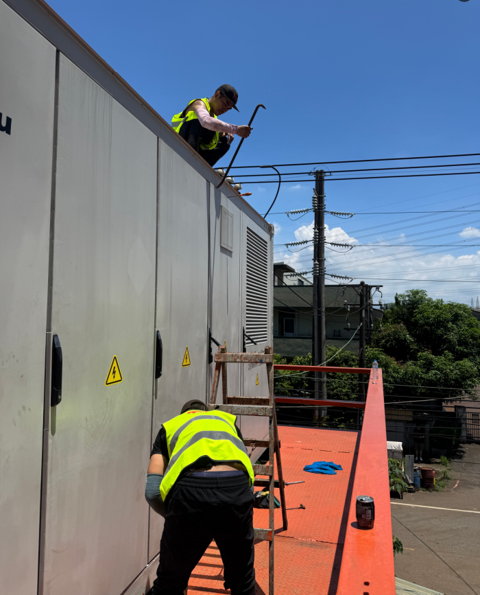
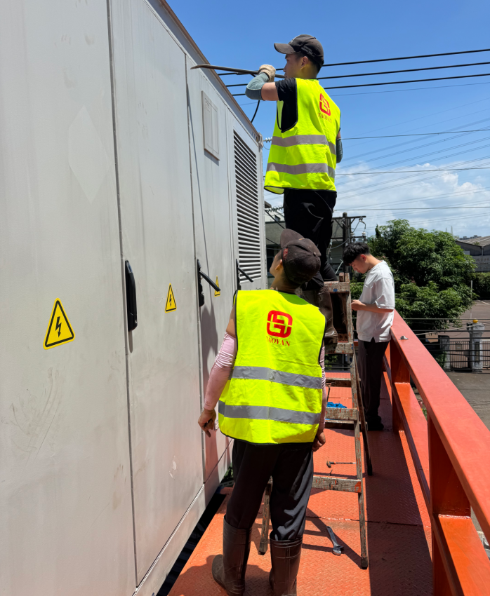
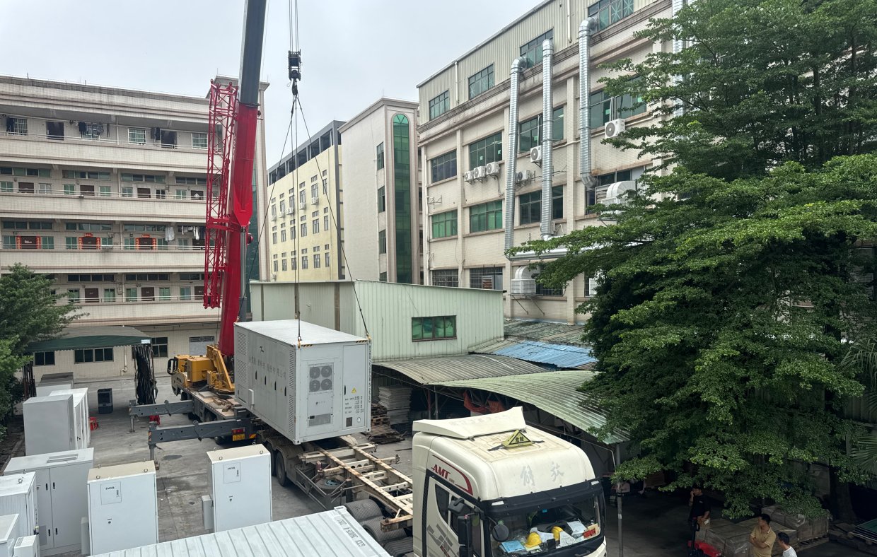
- Rapid Deployment: Single-container design eliminates need for dedicated battery building. Factory-tested complete unit transported to site, installed on concrete plinth with only grid connection required. 25-tonne total weight.
Project Images
Battery System Specifications
| Battery Pack Parameters | |
|---|---|
| Cell Type | LFP – 314Ah Prismatic |
| Total Capacity | 2,610 kWh (2612.48 kWh) |
| Battery Configuration | 10P260S (10 clusters × 260S) |
| Nominal Voltage | 832 V DC |
| Voltage Range | 748 V – 915 V DC |
| Operating Temperature | -25°C to 55°C |
| Cooling Method | Liquid-Cooled (Integrated Die-Cast Cold Plate) |
| Cycle Life | ≥ 8,000 cycles @ 80% DOD |
| Protection Rating | IP54 (Container) / IP67 (Module) |
| Max Altitude | ≤ 4,000 m |
| Dimensions (W×D×H) | 6,058 × 2,438 × 2,896 mm (20ft container) |
| Total Weight | ≈ 25 Tonnes |
| Battery Module Specifications | |
| Module Capacity | 52.25 kWh |
| Module Configuration | 1P52S (52 cells in series, 1 parallel) |
| Nominal Voltage | 166.4 V DC |
| Cell Capacity | 314 Ah |
| Module Dimensions (W×D×H) | 810 × 1,150 ×245 mm |
| Module Weight | 360 kg |
| Battery Cluster Specifications | |
| Cluster Capacity | 261.248 kWh |
| Cluster Configuration | 5 modules × 1P52S + High-Voltage Box |
| Nominal Voltage | 832 V DC |
| Working Voltage Range | 728 V – 936 V DC |
| Number of Clusters | 10 clusters per container |
Inverter & PCS Specifications
| PCS Parameters (EPCS1250-AS) | |
|---|---|
| Inverter Type | Grid-Tied (On-Grid) |
| Rated Output Power | 1,250 kW |
| Maximum Output Power | 1,300 kW |
| DC Voltage Range | 650 V – 950 V DC |
| Maximum DC Current | 1,630 A (163 A × 10 strings) |
| DC String Count | 10 strings |
| AC Rated Voltage | 400 V AC (3-phase 4-wire) |
| Grid Voltage Range | 320 V – 450 V AC |
| Maximum AC Current | 1,590 A |
| Rated Frequency | 50 / 60 Hz |
| Power Factor | > 0.99 (at rated power) |
| Power Factor Range | -1 (leading) ~ 1 (lagging) |
| Total Harmonic Distortion | < 3% (at rated power) |
| Maximum Efficiency | 98% |
| Cooling Method | Forced Fan Cooling |
| Noise Level | < 70 dB |
| Dimensions (W×D×H) | 1,600 × 1,000 × 2,400 mm |
| Weight | 750 kg (10 × 125kW modules) |
Container & Safety System Specifications
| Container Overview | |
|---|---|
| Container Type | 20ft Standard ISO Container |
| External Dimensions (L×W×H) | 6,058 × 2,438 × 2,896 mm |
| Total Weight | ≈ 25 Tonnes |
| Compartment Layout | Dual-chamber: Battery Chamber + Inverter Chamber |
| Battery Chamber Cooling | Liquid Cooling System (40kW refrigeration + PTC heating) |
| Inverter Chamber Cooling | Forced Air (fan cooling) |
| Protection Rating | IP54 (Container) / IP67 (Battery Module) |
| Fire Suppression System | |
| Agent Type | Heptafluoropropane (HFC-227ea) Gas + Dry Powder Backup |
| Fill Time | < 8 seconds (full battery chamber coverage) |
| Detection | Smoke sensors + Heat sensors + Acoustic/optical alarm |
| Safety Interlock | Automatic system shutdown upon detection; gas release indicator |
| BMS (Battery Management System) | |
| Architecture | 3-Level: BMU (module) → BCMU (cluster) → BAMS (array) |
| SOC Estimation Accuracy | ≤ 5% |
| Communication | CAN bus + RS485 + Ethernet |
| Key Functions | Real-time monitoring, cell balancing (passive), over/under voltage/current/temp protection, thermal management, event logging (128MB storage) |
| EMS (Energy Management System) | |
| Functions | Real-time monitoring, peak shaving scheduling, TOU optimization, remote dispatch, fault alarm, reporting, curve analysis |
| Protocol Support | MODBUS RTU/TCP |
| User Interface | Touchscreen HMI + Remote SCADA connectivity |
TAOYAN Energy Management System (EMS)
This project is equipped with TAOYAN’s self-developed Energy Management System (EMS) — a comprehensive monitoring, control, and revenue optimization platform designed specifically for industrial BESS deployments. The EMS provides real-time visibility into every aspect of the energy storage system, from individual cell-level data to grid-wide economic performance.
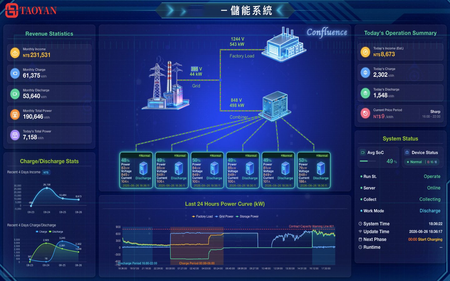
EMS Confluence Dashboard — Real-time system topology, unit status, revenue statistics & power curves
Core Capabilities
- System Topology Visualization: Interactive single-line diagram showing real-time power flow between Grid, Combiner, Battery Units, and Factory Load — with live voltage, current, and power readings at each node.
- Unit-Level Monitoring: Individual status for each battery cabinet — SoC %, charge/discharge power (kW), voltage (V), current (A), temperature, and health status with normal/warning/fault indicators.
- PCS Power & SoC Tracking: 24-hour rolling charts for PCS output power and battery State of Charge, enabling operators to verify scheduling execution and identify anomalies.
- Batch Control Panel: One-click operation mode switching between Manual Charge, Manual Discharge, All-weather Auto, and Scheduled modes — with immediate effect confirmation.
- Revenue Analytics: Daily/monthly/yearly income tracking broken down by tariff period (Sharp / Peak / Flat / Valley) with profit calculation based on Taiwan Power Company (Taipower) rate schedules.
- Charge/Discharge Statistics: Comprehensive kWh accounting with daily bar-chart comparison, cumulative totals, and exportable reports for financial reconciliation.
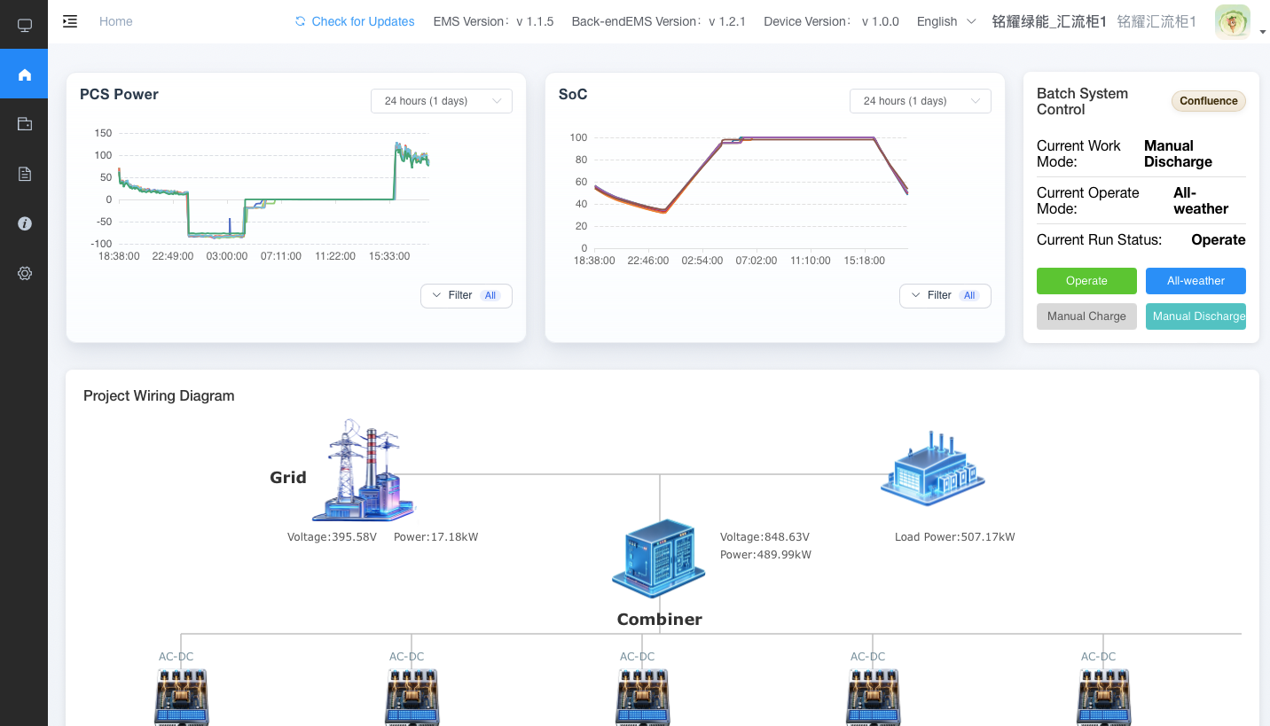
PCS Power curves, SoC tracking, batch control panel & real-time wiring diagram
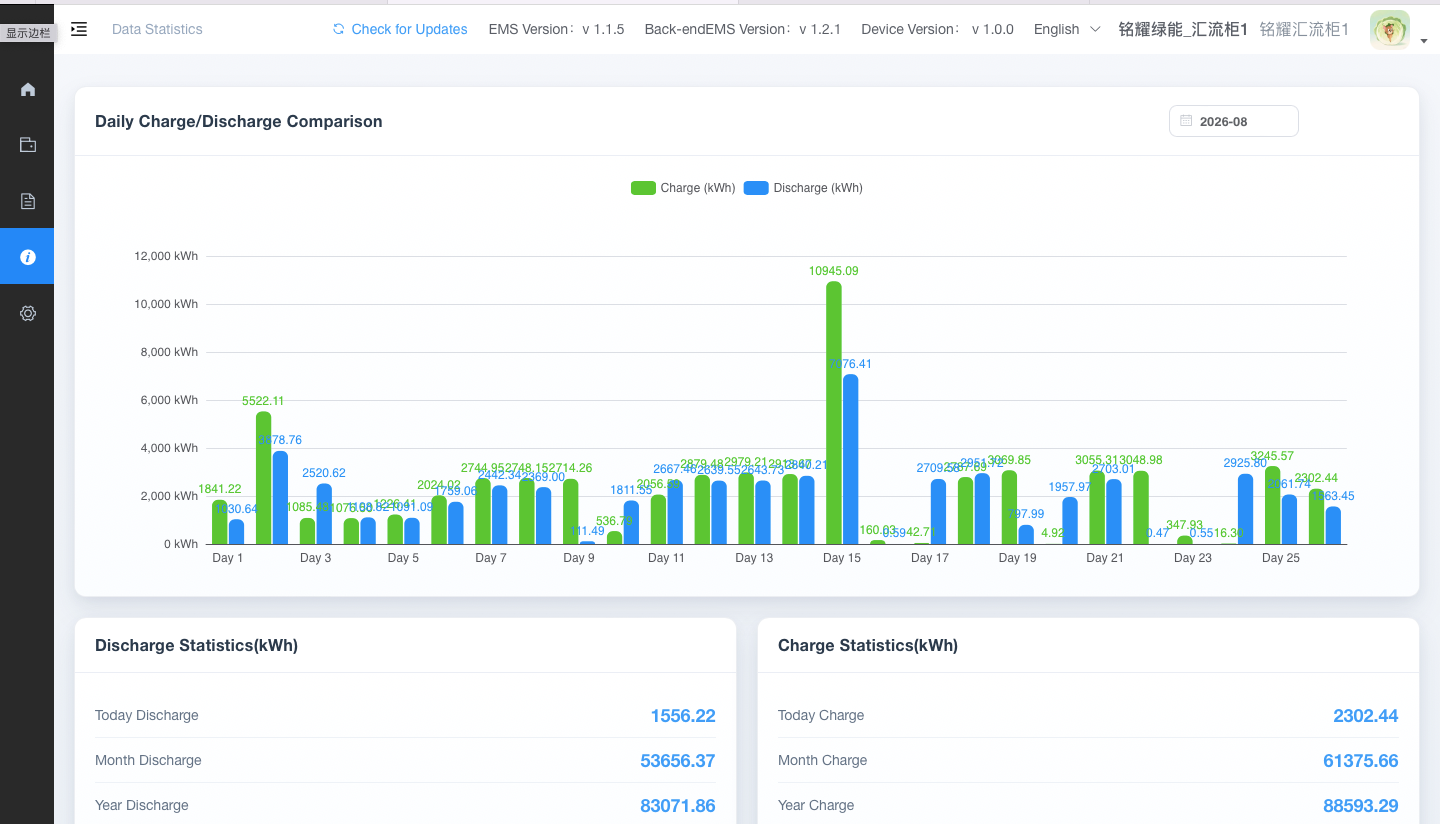
Daily charge/discharge comparison chart with period-based revenue breakdown